Sunday, November 1, 2020

Programming and testing the actuator

 Hi,

It's been a while since I last wrote, but it was mostly because I was engaged in writing my thesis and programming the actuator as well as writing a simple service app. Right now I'm testing the actuator and preparing a torque test stand in order to determine maximum torque and see if there is no severe cogging torque. 

I've made a few changes in the actuator design since the first prototype was made. A couple of parts (including the rotor) were milled with additional slots in order to make them lighter. 

these four slots result in 6g of mass reduction

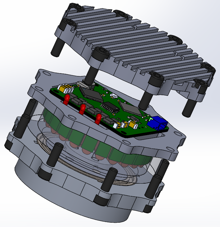
the rotor mounted in the case 

I also modified the stator mount part in order to place the rotor a bit lower than it was before. I gave up on three of four slots (initially made for motor cables) as I think they negatively influenced the heatsinking ability of the part. 

The gearbox housing was milled with eight additional slots and eight mounting threaded holes. Initially I wanted to use half of the motor gearbox screws for holding the motor to the external housing, but I decided to make additional threaded holes just for fixing the actuator. This solution looks much better and I do not have to use only four out of eight screws. 

Gearbox housing botom view

Moreover I milled the part that is used for connecting two actuators front-to-back. This was the most complicated part as there were many milling operations and the part required flipping. I even made a short time-lapse video about it :


The part itself: 


In order to reduce the backlash I modified the planet carrier pins to 3.1mm instead of 3mm (the gearbox planets holes are about 3.11 - 3.12mm in diameter which is not very convenient). There is still some play at the output, but at this point I cannot do anything about it, other than replacing the gearing system. For now it is okay. 

I prepared an early 3d-printed prototype of robot's leg: 

Leg prototype

The thigh is mounted to the knee actuator, whereas the knee actuator is mounted to the thigh actuator. This way the joints are independent which simplifies the mathematical analysis. The knee joint is driven by a belt. All three actuators were mounted as close to the torso as possible in order to make the leg light and reduce the moment of inertia. The adduction / abduction motor (hip actuator) is going to be placed in the robot's torso and connected to the thigh actuator. 

Besides mechanical parts modifications I made a simple python app for communicating with each actuator. The main purpose of the app is to be able to update the drivers' firmware by FD-CAN bus. Although there are some other functionalities such as spring/damper position control, offset measurement, motor parameters identification (d/q axis inductances and phase resistance used for PI controller gain calculations), setting the bounds within the motor should stay during the movement, or the live plot of measured quantities. So far it's been really useful in testing the motor and testing different ideas during development.

Service app - i know it looks awful ;)


In the end some high speed actuator tests that I performed recently: 


Hope you enjoyed this entry! Next time I'll do a quick writeup about the torque test bench and post some results ;)

You can follow me on Instagram for more frequent updates: https://www.instagram.com/klonyyy/


Friday, August 14, 2020

Machining the first motor module prototype

Recently I've written about the motor controllers, and now it's time for mechanical aspects of my project - the aluminum case holding the parts together. It took me about a week to finish a 3d model of the module. Then I 3d printed the parts, made some adjustments, and started milling the individual parts. The material used is PA6 aluminum (2017 T4511) bought in 70mm slices of different height. It is relatively cheap and easy accessible in my town (less than 8$ per kilo and ablut 1,5$ for band-saw cutting the slices). Milling in this material is very pleasant and at the same time mechanical properties of this aluminum alloy are sufficient for my purposes. While machining I did not have to use a lot of coolant (which is quite important as still use a plywood table). I mostly used IPA alcohol and WD-40 to cool down the part in moments where a lot of material was being removed. 

Now it is the photos time:


sun gear and bearing pressed onto the pin

I know the surface of the motor is sloppy it was done by hand, will fix it next time ;p

This part is the rotor extension so that I can press-fit a gear on it. The diameter step on the tip of the part is for bearing. It was milled from a 20mm PA6 aluminum cylinder.

Each 70mm cylinder slice was faced in order to get a flat reference point. Actually the one on the picture was earlier faced in the vice from other side, and this photo was made after facing from top side. 

I mostly used screws to fix the material to the table, as it was the fastest way considering I do not own any good claps yet. 


This is the lower part with PCB cap and stator press-fitted onto the cylinder. Now it is time for the distancing cylinder:


This was the part that required the most coolant as it is relatively thin and a lot of material has to be removed around it. I did not noticed any problems caused by overheating whatsoever. 

Probing the gearbox mount

slots made for internal gear's tabs 

though the endmill was a bit to big it looks nice and fits tightly!

lower planet carrier with additional sleeve for bearing ring

gearbox mount, top planet carrier, lower planet carrier ready to be assembled

And after milling the parts it was the time for assembling them: 


I'm really happy with the result, considering it was machined on a low cost DIY CNC machine. Of course it works - for now only in spring/damper mode (and open loop d/q voltages mode), but I'm working on a FDCAN communication app and more features right now. Hope you enjoyed it, and see you next time. 

I recently started documenting my projects on Instagram, so feel free to check it out: https://www.instagram.com/klonyyy/

Tuesday, July 28, 2020

Soldering new BLDC controllers

Hi!

I recently got the PCB's of my new brushless motor controller. It is also my first 4-layer design, so I was quite excited about it. I also ordered a stencil, so that the soldering is faster and more reliable. When the PCB's finally came to me I was very happy with the result. Although after a closer look I noticed some via problems. I do not know what is the origin of this problem, but these vias seem to be really bad quality.


At the same time the soldermask is very thin and literally scrapes off when being touched by hot soldering iron. I guess this it what you get for 13$ (JLCPCB) :) Although for prototyping purposes this offer is a great deal as 13$ is super low price for a 4-layer design and I still haven't seen a similar offer anywhere else.

I found an issue with the MOSFETs after soldering them to the pads. One of these two pieces of drain connector sticking on both sides was shorting motor terminal to V+. I had to move each low side FET a bit further from the pad to get rid of this issue. It turned out that my FET library wasn't precise enough (missed these two insets), but fortunately it is an easy bug to fix in the next iteration.

Whoops
The board seems to work fine after all, although I'm still struggling with a noise problem described in more detail at: https://e2e.ti.com/support/motor-drivers/f/38/p/921831/3423441#3423441. I hope the TI guys will help me to solve it soon ;)

In the end a few photos of the assembly process and assembled board:


Next time I'm going to show the mechanical structure of the motor module, as well as some photos of machining the individual parts. A little teaser:


Friday, July 3, 2020

CNC machine Z axis replacement

This time it will be a short entry about the milling machine and Z axis changes. Two weeks ago I received my 300mm long 20mm linear rails. I ordered them in the first place because the supported shafts had too much play, and thus the dimensions in y axis were a few hundreds off. New design is a lot stiffer and has roughly 140mm movement range comparing to 110mm achieved on supported shafts. The most important thing is that they have no play that can be seen with the naked eye. I will share the results, when I do the measurements using dial indicator. Again the parts were milled from a plywood plate on a bigger CNC machine in order to detect any possible issues without spending a lot of money on the materials. Some photos as always:

Z axis before modification

Linear rails in place as well as the ball screw

Finished!

Another thing I guess is worth sharing, is the chip protection for the lower linear rails and ball screw (y axis). I wanted to make curtains following the table - something similar to window blinds. I had to prepare a mechanism for folding and unfolding the curtains when the table moves. The simplest idea I came across was to use torsion springs from cheap folding rules. I 3d-printed my own casings, inserted the springs, added a bearing on each side and used a pvc tube as the shaft. The curtain is mounted to the table using slats with a few screw holes. The whole thing is quite nice-looking and most importantly keeps the chips away from the rails and ball screw. 

Mounting process
Inserting the spring


A video of the solution:

The last thing is just an interesting video of drilling using a blunt drill. When you look closely there is a visible heat wave coming off the hole when the drill pushes down on the part :)


Wednesday, June 10, 2020

DC motor controller

Hi!

This time I'd like to focus on a project I have made for a class at my university. It's a DC brushed motor controller. It is actually a part of a bigger project - an autonomous quad bike. Guys working at the mechanical aspects of the robot needed some powerful servos for operating the cluth, trottle, breaks and of course turning. They tested that the windshield wipers motors' have enough torque to move the mechanical components controlling the vehicle. I volunteered to design the control electronics board for such a motor and here I'd like to document the build with some photos and a few words of description.

I think the hardest part was to design the power supply section. The assumption was that the board should be able to be powered with voltages ranging from 12 to 24V. Actually the design can withstand voltages as high as 30V, because the acid batteries can exceed the 24V nominal voltage value by a few volts. The device needs a 4 different voltage levels to operate correctly. I think the diagram below explains the situation in a most explicit way:

Different supply voltages 
As can be seen on the above picture there are quite a few devices to power. There is a main DC/DC converter making a 5V output that powers the CAN transceiver. The LDO takes 5V and converts it to 3.3V for the STM32 microcontroller and the encoder. 15V power supply for the MOSFET drivers is outputted by an LDO. This was quite a tricky part of the design as I thought it could get hot due to the big voltage drop and some current flowing trough it. Running a simple simulation in LTSpice showed that the drivers can consume up to 40mA RMS, which would correspond to about 0.5W dissipated by the IC. Even though it would still operate in it's nominal conditions (about 100*C on the junction) I expected the power consumption to be much lower (as I simulated the worst scenario). I added some ceramic capacitors in close proximity to the LDO and the overall temperature is low enough to touch with a finger (<50*C). Finally the 30V is fed to the H bridge.

The device has a shunt resistor for current sensing. I thought about using the current measurement as a low resolution encoder. Below you can see an image of the motor current (blue waveform). The idea was to apply a low-pass filter and read the peaks as impulses, as they occur regularly. I imagine this regularity can be affected by the motor wear after some time, but it may still be an interesting source of motor position information.
Motor current waveforms - shunt voltage drop - purple, amplifier output - blue. 
The communication is performed using CAN bus, and for now it supports only one data frame with desired angular position. Maybe in the future the command list it will be expanded. Besides I think the rest is quite straightforward, so I'll just skip to the interesting part - the prototyping process and photos:

Planning the table

First layer

Milling process completed 

Milling some mild steel with a 6mm 4 flute milling cutter

Prototype mounted on the motor gear case.
 The prototype took me about three hours to make, but it allowed to find some bugs, like no op amp biasing, and poor performance of the way it was mounted on the motor. During the testing I set the current to 10A and voltage to about 28V and moved the motor each way with 90% PWM duty. My colleques stopped the shaft and we observed for extensive heating or any other signs of poor performance under load. After a few cycles the motor ran only in one direction while the other seemed to short the power supply. I suspected that we reached the limit of the MOSFETS, but it was kind of weird as they were cool to touch. The cause of this problem was the motor itself. Inside it has 3 brushes on the commutator for different operating velocities. The unused brush, although earlier dissconnected from the case potential, caused a short between one of the motor terminals and the case, to which the pcb was connected. After removing the brush everything was functional again. This situation, and the requirement of the controller to be water-resistant, dictated the shape of the PCB. Now it is rectangular and fits in a 3D printed case (for now).

JLC PCB board 

Almost finished 
One cool solution is the usage of the motor's built in limit switch. It is used for finding the zero position, when the encoder is in the incremental mode.

Next time I'll write a short description of the milling machine Z axis replacement, as the linear rails have arrived.