This time I'd like to finally share my bachelor's thesis with you. I couldn't do that earlier due to some internal regulations of my university, but since over six months have already passed I'm free to publish it by myself.
Before you take a look at it I must say it is not an innovative approach to the subject, but rather a report about a homemade brushless actuator. There might be some mistakes along the way as I'm still learning the motor control stuff, but hopefully you'll find it at least a bit interesting ;)
In this entry, I'll go over the Wolfie assembly process and in the end, I'll show you the full-body kinematics demo of the robot. It's been a very rewarding time for me, especially when I saw the robot stand on its feet for the first time :)
Let's start with the hip actuators mounted to the 3D-printed frame:
As you can see I started with assembling first four actuators and two opposing parts of the torso. I wanted to make sure the length of the power supply and CANFD cables I estimated is correct. They couldn't be too long as there is very little free space to fit all the actuators' cables. The two parts were joined by these side covers made from epoxy laminate. My initial idea was to make them from bent aluminum sheets, however, the bending process could be a little tricky without proper tools so I went for the laminate. I cut these on my CNC mill, making two grooves along the bend line:
Later on, I screwed them to the 3D printed frame and added epoxy adhesive in the grooves. This made them very stiff. Overall the robot structure feels stiff which is great, considering it is mostly held together by these two covers and the bottom plate. In the next revision (this is just a first prototype) I'll definitely go for inserts so that I can easily unscrew the side covers and the whole torso assembly.
Next up there were the four thigh actuators that are mounted to the hip actuator output harnesses:
As you can see I also prepared the cables for both hip and thigh actuators, and for latter pulled them through a special duct right to the inside of the torso. Tibia actuators were mounted in the end:
They whole actuator structure is actually pretty hard to assemble, but since it's just a hobby project I decided to leave it as it is and not optimize it for now :P.
I think just by looking at the last picture you can see the amount of connectors and cables inside the torso - its really dense in there. My plan was to use distribution PCBs like in the picture below:
unfortunately my PCB parcel got stuck in the customs and I had to mill these two by myself:
The cables look much nicer when these distribution boards are in place:
The laminate barrier part that you see inside the torso is just a piece of epoxy laminate with some nuts glued to it:
One of the last things was to put a sticky black foil on the covers so that they matched the rest of the assembly:
And finally! Wolfie the quadruped:
I know, its missing a few parts, but still it was a big event to put all the parts together :) Moreover I got it to move a bit:
This is just a simple demo, with kinematics implemented fully on the computer in a python script which then sends the commands to the actuators through USB<>FDCAN converter. When I finally receive the PCBs I will implement it on the raspberry PI so that it could be completely standalone.
In the end I want to mention the presentation about Wolfie which I gave during the Reddit r/Robotics Showcase. The whole event was recorded so feel free to check that out (my presentation starts at 01:04:30):
Now I want to tweak the walking algorithm which I'm not totally satisfied with (that's why I didn't publish it yet) and eventually implement some more advanced walking techniques, which require doing some more research :) I'll keep you posted!
as always I did not plan to make such a long break from documenting stuff, but this time I waited to finish preparing all the parts so that the photos are as good as they can get. Basically, this entry is about making the parts needed for the remaining nine actuators and an additional tenth actuator that's going to serve as a test unit.
The whole process took me around 1,5 months, but only because I had a few hours available every weekend (I did not want to mess up with my neighbours :P). The first step was to purchase the stock at a local company. I got around 5.5 kg of aluminium stock in 140mm diameter slices cut on a band saw.
The surface finish was quite bad so I had to face mill each side of each slice and then proceed with milling the parts. Besides face milling, each slice was drilled with seven holes to keep it fixed to the table. Each hole was widened on both sides of the slice so that the screw head could hide inside the material for the purpose of face milling.
Basically I've drilled seven 3mm holes, widened them at one end, screwed the stock to the table, face milled it, turned it around, widened holes by hand using a electric drill, screwed to the table and face milled on the other side as well. The whole process of face milling and drilling holes took me around one hour per two slices.
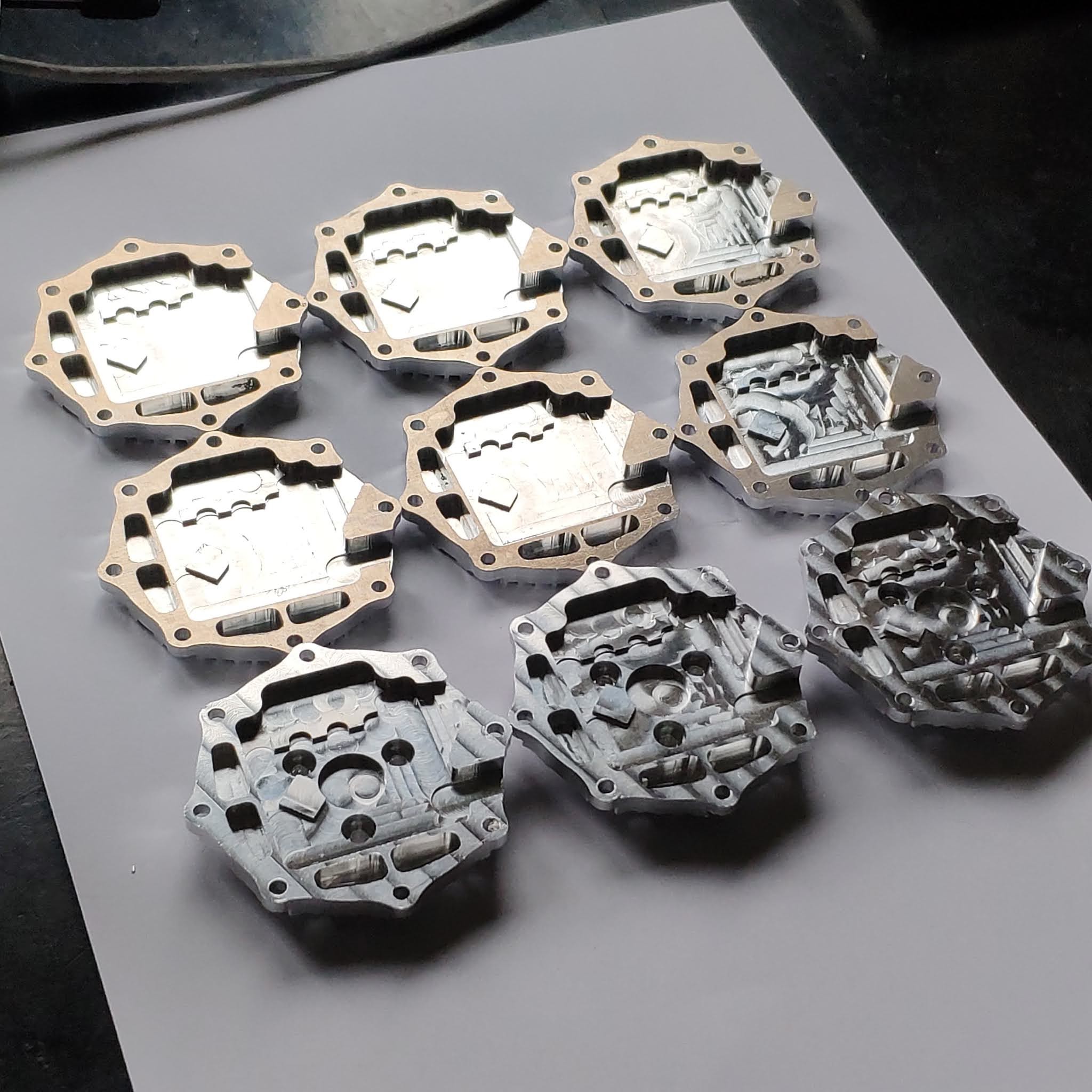
When first two slices were ready I could proceed with machining parts. I didn't have any particular plan, just started with the parts I've had the least. These were the motor base parts:
During milling I found some things I could optimize for example before I used to mill the distancing part without utilizing the material that's inside the part. It was just cut out and additionally had to be fixed so that it doesn't fly away. I found out that the material could be used to mill the planet carrier and there still will be enough material to cut the distancing part. Additionally the rest of material on the sides could be used to mill sungear mounts. I'm not the best at describing things so I prepared a photo - story of the process :
I like how these PCB caps present in the sunlight (these were actually cut out of a 6mm aluminum sheet, hence the brownish finish on the first six of them):
I wish I had flood coolant system, as after more aggressive cuts I had to wait for the part to cool down. Moreover I had to stand nearby with a vacuum cleaner to clear the chips in deeper grooves so that they don't build up. Anyway I'm happy with the overall result - the machine did just fine, without any major issues. After all, milling these parts was actually the reason it was created. Group photo:
After finishing all the custom parts I proceeded with motor parts and gears I had to modify slightly. The rotors were milled with four slots and the top surface was face-milled. The shaft was cut so that the encoder magnet could be glued onto it.
The thing I'm not particularly happy about is that five out of 12 actuators have the magnets glued to the shaft without any additional fixture. The rest is actually held in place using a miniature 2mm rod going through the shaft and the magnet, because the magnets have a small hole in the center. Unfortunately I ran out of stock on them and had to use regular ones.
The magnet on the right has a small 2mm hole which helps to align and properly fix it to the shaft
If anyone knows where to buy them (I got these from a friend of mine), I'd be grateful for leaving a comment.
Next I cut out the stators out of the original case. It was a long and stressful process as I didn't want to mess up the windings or the laminated steel sheets. I centered each motor in a vise and bored a hole through the aluminum case leaving only around 0.4 mm of material on each side. Then I manually milled the remaining material in two opposing spots and used a screwdriver to break the walls to the inside freeing the stator.
After that each stator was cleaned and a thermistor was glued in between the windings with expoxy.
The sungears had to be modified slightly as well. I had to mill two lobes on opposing sides so that they match the part that is screwed to the rotor. It was quite stressful as well and ended up with one broken tool (the 1.5mm 3 flute endmill) when I wanted to go a bit faster.
When these were ready I press-fitted them onto the aluminium shafts that are visible on the photos below.
As for now I've finished soldering the remaining PCBs, without testing them yet. Now it's time to press each stator onto the base part and make sure everything is hunky dory. Some pre-assembly family photos in the end:
The process of tiling these parts was tedious, but I'm really happy with the photos (could use some more light though).
Lately, I've been working on a few PCBs located in Wolfie's torso. In theory, there should be at least two PCB's - one responsible for power supply distribution (in my case called the "power board") and the other serving as SPI to CANFD converter equipped with an IMU, magnetometer, and wireless communication (in my case called the "control board").
the internals of the torso
Having talked to my friends from MABrobotics I decided to galvanically isolate the main computer and the control board from the high-power actuators to minimize the chances of damaging the control unit in case any bad things happen on the side of the actuators. At the same time, I didn't have any chance to play with isolated circuits before, so it seemed to be a great opportunity to learn some new stuff.
As there isn't much free space inside the torso and I didn't want to place the power board near RPI I had to go for a modular design. I decided to split it into the non-isolated base part and the optional isolation module. I think it is quite a reasonable solution because in case there's something wrong with the isolation part, I can always use the basic, non-isolated variant. After a short introduction let's have a look at the torso electronics diagram:
Starting from the left side, there is a 4S2P 16.8V Li-ion battery with a BMS integrated into the battery case (I plan on doing another write-up about the battery itself) and the main supply switch. Next, there's the power board PCB. It has a main shunt resistor that is used to measure the current going in for the whole system (ie. the actuators and control electronics). The small voltage drop is amplified using a current sense op-amp and the battery voltage is monitored using a voltage divider. Both voltage signals are fed to a connector that goes to the control board. In the basic variant (without isolation), RPI and control board power supply comes from a non-isolated DC/DC converter. The actuators are turned on and off using a HotSwap controller that is equipped with its own shunt resistor just for the actuators and controls three external MOSFETs.
Power board
In case the isolated part works properly in the first iteration the current amplifier and DC/DC converter are not going to be populated on the powerboard and the isolation module is going to be placed on top of it. The isolation module is equipped with an isolated DC/DC converter supplying the 5V bus (3A max), an isolated ADC, and a photocoupler for isolating the digital on/off signal for actuators. There are also two LDO's for the primary and secondary side of the ADC and actually, that's it. The main difference is that no analog voltage signals are connected to the control board, but rather an SPI bus that is used to read the ADC's readings.
Isolation module
There are only six connectors on the power board for powering the actuators, but these get multiplied on the front and back side using two small distribution boards like this:
CANFD bus and supply distribution board
I'm not particularly happy with them - I think they are really packed and kind of ruin the slick design on the inside of the robot, but trust me there's no other way. The robot is simply too small to fit that many connectors in any different area.
The blue rectangle on the main diagram is illustrating the components placed on the control board. The board is designed to fit as a "hat" on the Raspberry Pi. It has two G4 microcontrollers - one solely for CANFD communication with the actuators (the communication is isolated as well), the other working as orientation estimator (IMU+mag), taking care of wireless communication and SPI readings coming from the isolation module. It's also partially responsible (together with RPI) for controlling the actuators supply bus. In case the RPI or the navigation algorithm detects any faults they can, independently of each other, turn the actuators off.
Control board
I guess the explanation combined with the diagram will help to grasp the overall idea. The PCBs are going to be sent for manufacturing soon, but I'm mostly worried about the global IC shortages. We'll see how it goes - hopefully not messing up my plans :)
The next post is going to be about the custom battery I'm preparing right now ;)
I hope this entry will be more exciting than the previous ones, as I'm going to show you the working prototype of Wolfie's leg. The leg was built to confirm that the actuators can withstand high torques occurring while jumping. The setup completed more than 1000 jumps on the test stand and no failures were observed so I guess after some more testing I'll be ready to continue with making twelve of these :)
The test stand was built from parts I had lying around. That's why it is kind of ugly. Since it's just a tool to test the actuators I didn't pay special attention to aesthetic aspects. It has a plywood base to which a 400mm long 40x40 extruded aluminum column is mounted. The 8mm rails are the remains of my old printer which got disassembled (I have built a new one - will write about that soon ;)) and so is the cart with linear bearings. The rails are mounted to the top and bottom of the column so in the middle they appear to be a bit wobbly.
The hip of the leg was slightly modified to fit the cart and the rest of the leg remained unchanged. It is able to operate its all 3DoFs, however, due to lack of MOSFET transistors, I am unable to operate the hip joint for now. It's a subject for another discussion but long story short I had to replace the MOSFETS some time ago as I found that the ones I was using started to fail at higher voltages due to unknown reasons. I still find this very odd and want to do a more controlled comparison between the two (SIS862DN (failing even though it is "beefier" in parameters) and SISA88DN (which is working just fine)). So for now it's a 2DoF leg, but soon I'll be making an order for powerboard parts and I'll get these MOSFETS restocked.
Besides I modified the cabling so that the supply cables are thinner (AWG18 compared to AWG16) and I added some twisted CAN cables for improved noise immunity. Still thinking about the best way to route the cables inside the chassis, which is somewhat linked with the powerboard itself (that I'm currently designing).
Actually, there's not much more to it. I derived the kinematic equations once again just to find out that the ones from here are working just fine and are much shorter (I was unable to simplify my equations). Besides I wrote a simple python code to command the trajectory (in reality it's just a few points in space) through my CAN<>USB dongle. Eventually, this came out (sorry for the image aspect ratio - it was the only way to film the test stand without revealing the mess on the desk :P):
I'm pretty happy with the results. I managed to achieve 15cm of jump height and it could probably be more on a higher test stand and better rails. Moreover, nothing actuator-related failed which is great news. I was particularly worried about the sungear slipping on the shaft and breaking my double keyway connection or just a shaft fracture, but it didn't happen through the tests. The actuators remained cool, at around 30*C even after a few hundred jumps. The only thing that failed was the slipping belt that drives the knee. It turned out that it was not tensioned properly and slipped under big loads. This was resolved by making the leg 1 mm longer so that the belt was initially tensioned and could be tensioned even more with screw tensioners.
Another failure, that was kind of expected (and isn't taken into account :P), was the rubber material on the foot. For the initial prototype, I have used a very soft (20 shoreA) urethane rubber that I had lying around, just to test my mold and the foot design itself. During testing, the soft rubber got squished and broke off the foot. I have to do some research for a better foot material for sure.
Anyway, this is probably all I've got for today. Currently, I'm working on a powerboard PCB and battery pack design, so soon I'll post something about that ;)
Recently, I haven't posted any updates as I was completely absorbed with my bachelor's thesis. Thankfully, it's almost finished and I'll have some more time for the actuators and quadruped robot soon. This post is going to be short, but I want to post the static torque data that I said I would, but most probably I forgot. So here it is:
The test bench consists of a single motor, dynamic torque transducer (it was purchased by our sumo robot club to measure both static and dynamic torques), and a lever to fix the other end of the transducer's shaft to the test bench. Obviously for now the sensor works only in the static scenario. The motor was commanded with incrementally increasing q currents and the measured torque was plotted. I tried to cool the motor down to room temperature before each run in order to minimize the influence of increased temperature.
It was able to produce 3Nm of peak torque at about 35A of q-axis current (near 10A on the power supply). The torque constant was determined to be roughly 0.125Nm/A in the linear range. After commanding currents above 25A the motor starts to saturate, so the torque performance is reduced and the motor is heating very quickly. Overall I'm happy with the results, 3Nm of maximum torque should be sufficient to perform basic types of gaits. Especially if I make the quadruped structure lightweight.
Today I'd like to post some thermal data that I've gathered recently. I wanted to check what is the maximum continuous torque of my motor module. By continuous I mean the amount of torque the motor is able to produce infinitely without overheating. It seems that many actuator manufacturers interpret "continuous torque" differently - sometimes by continuous they mean a short period of time, which is far from being continuous (Josh made a similar observation in his log: https://jpieper.com/2020/08/07/up-rating-the-qdd100-beta-thermal-bounds/). I decided to test my actuators and determine what is their continuous torque rating. The test stand was rather simple - an actuator with a lever pushing against a table.
I was simply commanding different torque values and waiting for the actuator to heat up. This was quite a monotonous process as the estimated time constant was about 16 minutes and I stopped each experiment after a duration of five time constants (almost 1,5h).
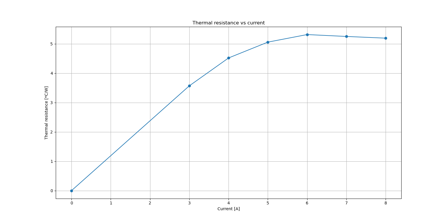
I wanted to go one step further and prepare a simple first order system model. After all the thermal circuit can be modelled similarly to a simple parallel RC circuit, where the resistance is the thermal resistance form the module to air, capacitance is the thermal capacitance, voltage is temperature and current is power loss. The input to the system is power loss that occurs on the winding resistance. The model is able to fit a single curve, however due to changing thermal resistance to ambient it is no good in predicting a few different responses. This is the outcome:
The ambient temperature was about 25*C, and the actuator initial temperature was 30*C.
As you can see the thermal resistance varies with different currents being applied. This is why it is so hard to predict the resultant temperature response based solely on the current. Nevertheless the real characteristics helped me to determine the maximum continuous torque which is 0.875Nm (7A), and with that current the device should never reach 65*C.
In the next entry i'm going to publish some static torque data.
It's been a while since I last wrote, but it was mostly because I was engaged in writing my thesis and programming the actuator as well as writing a simple service app. Right now I'm testing the actuator and preparing a torque test stand in order to determine maximum torque and see if there is no severe cogging torque.
I've made a few changes in the actuator design since the first prototype was made. A couple of parts (including the rotor) were milled with additional slots in order to make them lighter.
these four slots result in 6g of mass reduction
the rotor mounted in the case
I also modified the stator mount part in order to place the rotor a bit lower than it was before. I gave up on three of four slots (initially made for motor cables) as I think they negatively influenced the heatsinking ability of the part.
The gearbox housing was milled with eight additional slots and eight mounting threaded holes. Initially I wanted to use half of the motor gearbox screws for holding the motor to the external housing, but I decided to make additional threaded holes just for fixing the actuator. This solution looks much better and I do not have to use only four out of eight screws.
Gearbox housing botom view
Moreover I milled the part that is used for connecting two actuators front-to-back. This was the most complicated part as there were many milling operations and the part required flipping. I even made a short time-lapse video about it :
The part itself:
In order to reduce the backlash I modified the planet carrier pins to 3.1mm instead of 3mm (the gearbox planets holes are about 3.11 - 3.12mm in diameter which is not very convenient). There is still some play at the output, but at this point I cannot do anything about it, other than replacing the gearing system. For now it is okay.
I prepared an early 3d-printed prototype of robot's leg:
Leg prototype
The thigh is mounted to the knee actuator, whereas the knee actuator is mounted to the thigh actuator. This way the joints are independent which simplifies the mathematical analysis. The knee joint is driven by a belt. All three actuators were mounted as close to the torso as possible in order to make the leg light and reduce the moment of inertia. The adduction / abduction motor (hip actuator) is going to be placed in the robot's torso and connected to the thigh actuator.
Besides mechanical parts modifications I made a simple python app for communicating with each actuator. The main purpose of the app is to be able to update the drivers' firmware by FD-CAN bus. Although there are some other functionalities such as spring/damper position control, offset measurement, motor parameters identification (d/q axis inductances and phase resistance used for PI controller gain calculations), setting the bounds within the motor should stay during the movement, or the live plot of measured quantities. So far it's been really useful in testing the motor and testing different ideas during development.
Service app - i know it looks awful ;)
In the end some high speed actuator tests that I performed recently:
Hope you enjoyed this entry! Next time I'll do a quick writeup about the torque test bench and post some results ;)
You can follow me on Instagram for more frequent updates: https://www.instagram.com/klonyyy/