Hello again,
as always I did not plan to make such a long break from documenting stuff, but this time I waited to finish preparing all the parts so that the photos are as good as they can get. Basically, this entry is about making the parts needed for the remaining nine actuators and an additional tenth actuator that's going to serve as a test unit.
The whole process took me around 1,5 months, but only because I had a few hours available every weekend (I did not want to mess up with my neighbours :P). The first step was to purchase the stock at a local company. I got around 5.5 kg of aluminium stock in 140mm diameter slices cut on a band saw.
The surface finish was quite bad so I had to face mill each side of each slice and then proceed with milling the parts. Besides face milling, each slice was drilled with seven holes to keep it fixed to the table. Each hole was widened on both sides of the slice so that the screw head could hide inside the material for the purpose of face milling.
Basically I've drilled seven 3mm holes, widened them at one end, screwed the stock to the table, face milled it, turned it around, widened holes by hand using a electric drill, screwed to the table and face milled on the other side as well. The whole process of face milling and drilling holes took me around one hour per two slices.
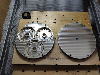
When first two slices were ready I could proceed with machining parts. I didn't have any particular plan, just started with the parts I've had the least. These were the motor base parts:
During milling I found some things I could optimize for example before I used to mill the distancing part without utilizing the material that's inside the part. It was just cut out and additionally had to be fixed so that it doesn't fly away. I found out that the material could be used to mill the planet carrier and there still will be enough material to cut the distancing part. Additionally the rest of material on the sides could be used to mill sungear mounts. I'm not the best at describing things so I prepared a photo - story of the process :
I wish I had flood coolant system, as after more aggressive cuts I had to wait for the part to cool down. Moreover I had to stand nearby with a vacuum cleaner to clear the chips in deeper grooves so that they don't build up. Anyway I'm happy with the overall result - the machine did just fine, without any major issues. After all, milling these parts was actually the reason it was created. Group photo:
After finishing all the custom parts I proceeded with motor parts and gears I had to modify slightly. The rotors were milled with four slots and the top surface was face-milled. The shaft was cut so that the encoder magnet could be glued onto it.
The thing I'm not particularly happy about is that five out of 12 actuators have the magnets glued to the shaft without any additional fixture. The rest is actually held in place using a miniature 2mm rod going through the shaft and the magnet, because the magnets have a small hole in the center. Unfortunately I ran out of stock on them and had to use regular ones. |
| The magnet on the right has a small 2mm hole which helps to align and properly fix it to the shaft |
If anyone knows where to buy them (I got these from a friend of mine), I'd be grateful for leaving a comment.
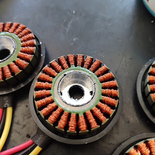
Next I cut out the stators out of the original case. It was a long and stressful process as I didn't want to mess up the windings or the laminated steel sheets. I centered each motor in a vise and bored a hole through the aluminum case leaving only around 0.4 mm of material on each side. Then I manually milled the remaining material in two opposing spots and used a screwdriver to break the walls to the inside freeing the stator.
After that each stator was cleaned and a thermistor was glued in between the windings with expoxy.
The sungears had to be modified slightly as well. I had to mill two lobes on opposing sides so that they match the part that is screwed to the rotor. It was quite stressful as well and ended up with one broken tool (the 1.5mm 3 flute endmill) when I wanted to go a bit faster.
When these were ready I press-fitted them onto the aluminium shafts that are visible on the photos below.
As for now I've finished soldering the remaining PCBs, without testing them yet. Now it's time to press each stator onto the base part and make sure everything is hunky dory. Some pre-assembly family photos in the end:
The process of tiling these parts was tedious, but I'm really happy with the photos (could use some more light though).


