Tuesday, July 28, 2020

Soldering new BLDC controllers

Hi!

I recently got the PCB's of my new brushless motor controller. It is also my first 4-layer design, so I was quite excited about it. I also ordered a stencil, so that the soldering is faster and more reliable. When the PCB's finally came to me I was very happy with the result. Although after a closer look I noticed some via problems. I do not know what is the origin of this problem, but these vias seem to be really bad quality.


At the same time the soldermask is very thin and literally scrapes off when being touched by hot soldering iron. I guess this it what you get for 13$ (JLCPCB) :) Although for prototyping purposes this offer is a great deal as 13$ is super low price for a 4-layer design and I still haven't seen a similar offer anywhere else.

I found an issue with the MOSFETs after soldering them to the pads. One of these two pieces of drain connector sticking on both sides was shorting motor terminal to V+. I had to move each low side FET a bit further from the pad to get rid of this issue. It turned out that my FET library wasn't precise enough (missed these two insets), but fortunately it is an easy bug to fix in the next iteration.

Whoops
The board seems to work fine after all, although I'm still struggling with a noise problem described in more detail at: https://e2e.ti.com/support/motor-drivers/f/38/p/921831/3423441#3423441. I hope the TI guys will help me to solve it soon ;)

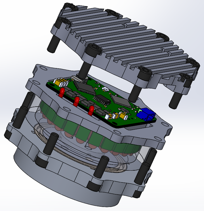
In the end a few photos of the assembly process and assembled board:


Next time I'm going to show the mechanical structure of the motor module, as well as some photos of machining the individual parts. A little teaser:


Friday, July 3, 2020

CNC machine Z axis replacement

This time it will be a short entry about the milling machine and Z axis changes. Two weeks ago I received my 300mm long 20mm linear rails. I ordered them in the first place because the supported shafts had too much play, and thus the dimensions in y axis were a few hundreds off. New design is a lot stiffer and has roughly 140mm movement range comparing to 110mm achieved on supported shafts. The most important thing is that they have no play that can be seen with the naked eye. I will share the results, when I do the measurements using dial indicator. Again the parts were milled from a plywood plate on a bigger CNC machine in order to detect any possible issues without spending a lot of money on the materials. Some photos as always:

Z axis before modification

Linear rails in place as well as the ball screw

Finished!

Another thing I guess is worth sharing, is the chip protection for the lower linear rails and ball screw (y axis). I wanted to make curtains following the table - something similar to window blinds. I had to prepare a mechanism for folding and unfolding the curtains when the table moves. The simplest idea I came across was to use torsion springs from cheap folding rules. I 3d-printed my own casings, inserted the springs, added a bearing on each side and used a pvc tube as the shaft. The curtain is mounted to the table using slats with a few screw holes. The whole thing is quite nice-looking and most importantly keeps the chips away from the rails and ball screw. 

Mounting process
Inserting the spring


A video of the solution:

The last thing is just an interesting video of drilling using a blunt drill. When you look closely there is a visible heat wave coming off the hole when the drill pushes down on the part :)