Saturday, November 21, 2020

Actuator thermal testing

 Hi

Today I'd like to post some thermal data that I've gathered recently. I wanted to check what is the maximum continuous torque of my motor module. By continuous I mean the amount of torque the motor is able to produce infinitely without overheating.  It seems that many actuator manufacturers  interpret "continuous torque" differently - sometimes by continuous they mean a short period of time, which is far from being continuous (Josh made a similar observation in his log: https://jpieper.com/2020/08/07/up-rating-the-qdd100-beta-thermal-bounds/). I decided to test my actuators and determine what is their continuous torque rating. The test stand was rather simple - an actuator with  a lever pushing against a table. 

I was simply commanding different torque values and waiting for the actuator to heat up. This was quite a monotonous process as the estimated time constant was about 16 minutes and I stopped each experiment after a duration of five time constants (almost 1,5h). 

I wanted to go one step further and prepare a simple first order system model.  After all the thermal circuit can be modelled similarly to a simple parallel RC circuit, where the resistance is the thermal resistance form the module to air, capacitance is the thermal capacitance, voltage is temperature and current is power loss. The input to the system is power loss that occurs on the winding resistance. The model is able to fit a single curve, however due to changing thermal resistance to ambient it is no good in predicting a few different responses. This is the outcome: 

The ambient temperature was about 25*C, and the actuator initial temperature was 30*C.

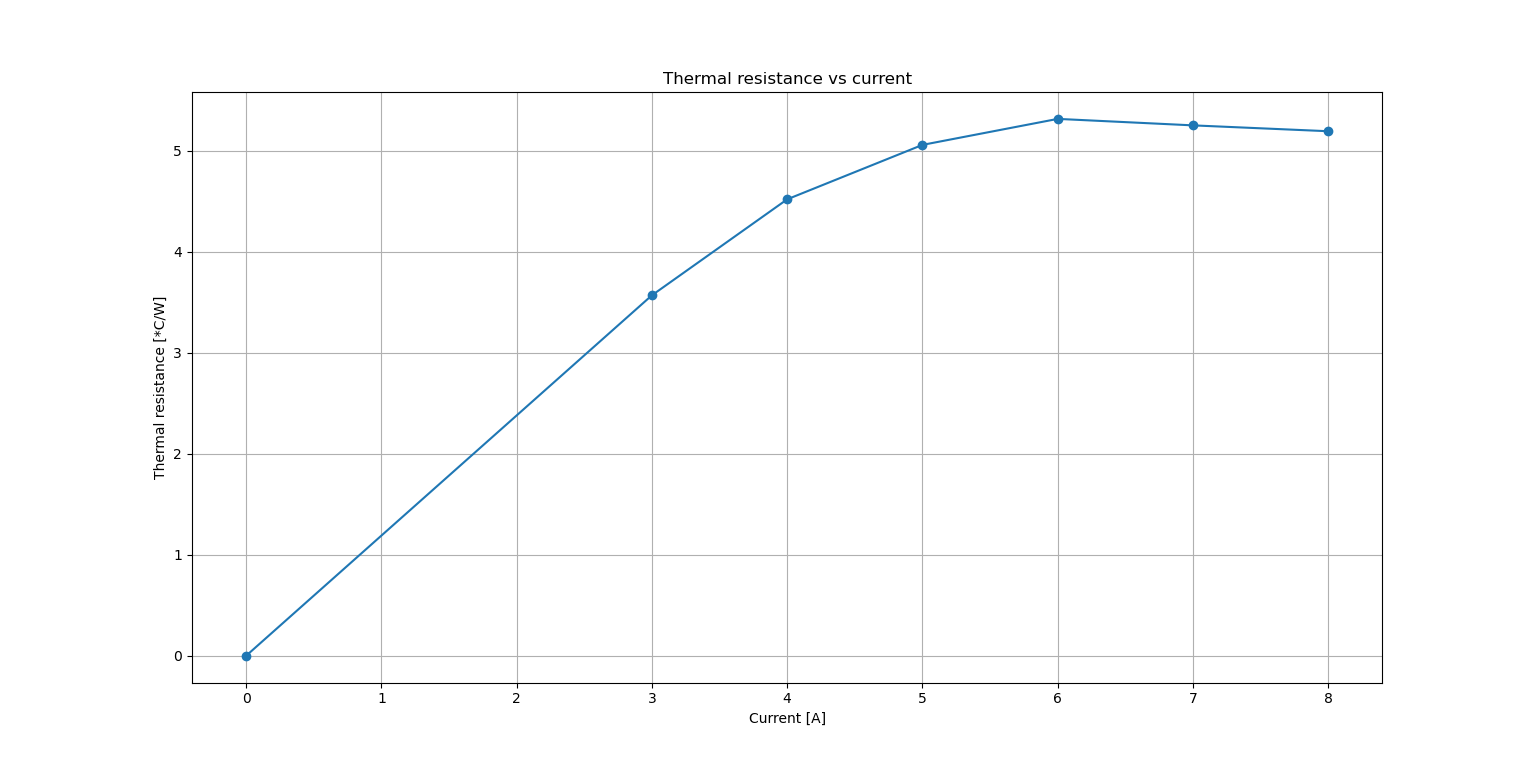
As you can see the thermal resistance varies with different currents being applied. This is why it is so hard to predict the resultant temperature response based solely on the current. Nevertheless the real characteristics helped me to determine the maximum continuous torque which is 0.875Nm (7A), and with that current the device should never reach 65*C. 

In the next entry i'm going to publish some static torque data. 

Tuesday, November 17, 2020

New method of fixing the sun gear to the shaft

 Hi,

this is going to be just a short log about new way of fixing the sun gear to the aluminium shaft mounted to the rotor. During some high speed tests of the actuator I noticed that the sun gear slipped on the aluminium axis when I tried to stop the output 3d-printed lever. I was kind of expecting it as I haven't made a strong interference fit and used just a regular epoxy adhesive and paid no extra attention to that part. I decided to try some new methods. 

The first idea was to make a hole in the aluminium stock before milling, and then mill the motor shaft part so that the shaft has this long groove. A similar groove was milled in the sun gear as well. As you might expect it was supposed to be a keyway connection. The key was simply a piece of mild steel screw shaped to fit the empty space. 

before pressing in the key

After pressing the key


The connection looked ok, but was a bit springy when I tried to break it using pliers. I succeeded eventually and saw the shaft was weakened by the groove. 

broken connection


The second idea was to make something like a shape connection (I do not know the professional name) where the shaft and gear are milled with a matching shape and then just pressed onto each other. This connection does not require additional elements, however it is inevitable to avoid the rounded edges when milling the shaft "tab". The rounded corners favor breaking the gear by pushing on its walls outwards. 

"shape fit"
This kind of connection weakened the gear and when I tried to break it I just broke the gear. It could be influenced by the additional force exerted by the pliers as well, but I did not want to take that chance. 

The last idea was to make two small tabs on the shaft (making it more rigid as well) and two grooves of the same shape in the gear. However the tabs were substantial smaller, and they reached only half of gear's length. The rest was just a normal shaft, though slightly larger in order to make a strong connection when the gear is press fitted onto it. 

Two small tabs milled with 6mm endmill

Two small grooves made with 1,5mm endmill

The two parts were cleaned with alcohol and epoxy adhesive was applied on the contact surfaces. I used a vise and slowly pressed the gear onto the shaft. I haven't really tried to break this part manually, however I mounted it in the motor module and till now it survived a few hard shocks and about 0.45Nm of continuous torque (on the motor shaft). 

If it fails I'll try adding loctite adhesive, but hopefully this connection will be strong enough ;) 


Sunday, November 1, 2020

Programming and testing the actuator

 Hi,

It's been a while since I last wrote, but it was mostly because I was engaged in writing my thesis and programming the actuator as well as writing a simple service app. Right now I'm testing the actuator and preparing a torque test stand in order to determine maximum torque and see if there is no severe cogging torque. 

I've made a few changes in the actuator design since the first prototype was made. A couple of parts (including the rotor) were milled with additional slots in order to make them lighter. 

these four slots result in 6g of mass reduction

the rotor mounted in the case 

I also modified the stator mount part in order to place the rotor a bit lower than it was before. I gave up on three of four slots (initially made for motor cables) as I think they negatively influenced the heatsinking ability of the part. 

The gearbox housing was milled with eight additional slots and eight mounting threaded holes. Initially I wanted to use half of the motor gearbox screws for holding the motor to the external housing, but I decided to make additional threaded holes just for fixing the actuator. This solution looks much better and I do not have to use only four out of eight screws. 

Gearbox housing botom view

Moreover I milled the part that is used for connecting two actuators front-to-back. This was the most complicated part as there were many milling operations and the part required flipping. I even made a short time-lapse video about it :


The part itself: 


In order to reduce the backlash I modified the planet carrier pins to 3.1mm instead of 3mm (the gearbox planets holes are about 3.11 - 3.12mm in diameter which is not very convenient). There is still some play at the output, but at this point I cannot do anything about it, other than replacing the gearing system. For now it is okay. 

I prepared an early 3d-printed prototype of robot's leg: 

Leg prototype

The thigh is mounted to the knee actuator, whereas the knee actuator is mounted to the thigh actuator. This way the joints are independent which simplifies the mathematical analysis. The knee joint is driven by a belt. All three actuators were mounted as close to the torso as possible in order to make the leg light and reduce the moment of inertia. The adduction / abduction motor (hip actuator) is going to be placed in the robot's torso and connected to the thigh actuator. 

Besides mechanical parts modifications I made a simple python app for communicating with each actuator. The main purpose of the app is to be able to update the drivers' firmware by FD-CAN bus. Although there are some other functionalities such as spring/damper position control, offset measurement, motor parameters identification (d/q axis inductances and phase resistance used for PI controller gain calculations), setting the bounds within the motor should stay during the movement, or the live plot of measured quantities. So far it's been really useful in testing the motor and testing different ideas during development.

Service app - i know it looks awful ;)


In the end some high speed actuator tests that I performed recently: 


Hope you enjoyed this entry! Next time I'll do a quick writeup about the torque test bench and post some results ;)

You can follow me on Instagram for more frequent updates: https://www.instagram.com/klonyyy/