Thursday, September 14, 2023

STMViewer update: Trace Viewer module

 Hello, 


Today I want to give you a quick tour of the latest STMViewer update.


The update introduces a new module in the STMViewer which is called Trace Viewer. It serves as a visualizer for trace data read using an ST-Link programmer. SWO output is usually used to print messages from an embedded target to a console on the PC. However, I think there is an even better application for this excellent piece of hardware installed in Cortex M3/M4/M7/M33 cores. Since the trace output can be really fast, and the protocol is designed in a very bandwidth-efficient way (I might make a separate post about it someday), we can send a lot of data with precise timestamps that are automatically added by the trace peripheral. This sounds like a perfect way for profiling parts of a codebase, displaying interrupts and their durations, checking if a timer is configured properly, or displaying very fast "analog" signals, like ADC measurements. What's even better is that you only need one additional pin except SWDIO, SWCLK, and GND - the SWO pin. 


To send a byte with a so-called, "local timestamp" you simply write a register of the ITM peripheral (Instrumentation Trace Macrocell) like so:


ITM->PORT[<number>] .u8 = value; 


That's simple, isn't it? For the STMViewer to interpret the data as a high state you have to send 0xaa byte, for a low state you have to send 0xbb byte. You can also switch each channel to the "analog" domain and send full 8-,16- and 32-bit values that will be displayed. 


There is no need to configure the ITM peripheral as STMViewer does it using the debug interface on each trace start.


Below is a short demonstration GIF. In the beginning, you can see three digital channels of interrupts with different priorities (the highest priority is the top one, lowest is the bottom one). Preemption can be easily spotted by looking at the varying CH3 frequency. By using markers one can measure the time between two actions represented on the trace plots. Notice that the SysTick interrupt takes around 200ns (!) to complete and it's easily registered among much slower signals. 


The other part of the GIF shows a fast analog signal (each new sample is created every 10us) in combination with a high-priority interrupt that performs a memcopy of a large buffer.


This is just a demonstration, not a real application, however, I believe it will help to understand the use cases for this new STMViewer module. 


Please see the README.md file for a quick startup guide. 


Be sure to let me know if you have any feedback or feature ideas. Happy debugging! 

Sunday, June 11, 2023

STMViewer - visualize your embedded data in real-time


Hey,

This entry is going to be a software one or rather one about a software tool that I've been developing for a few months now - STMViewer:


Currently, I'm working at MAB Robotics, where I work on various stuff around MD80 brushless motor controllers, mostly software-related. The software stack incorporates a couple of control loops, with many tuning parameters and variables that should be observed in real-time to make sure the drive is operating correctly.

I’ve been using STMStudio for that purpose since it offers a high update rate data visualization without intervening in the software execution. All you need is the programmer that usually is connected to the target anyways during the development stage. STMStudio would be totally enough if it would be still supported, however, ST decided to abandon that project and currently, it is declared NRND. It has some annoying bugs; for example, it doesn’t support C++ mangled names directly using the list variables option (typing the names manually works, but sometimes it stops updating the addresses, no idea why). Moreover, it is only available for Windows. The CubeMonitor which should be the STMStudio’s successor turned out to be a disaster even though it seemed to have an interesting idea behind it, and it looks like its abandoned as well. Having no other options I decided to make my own real-time data visualizer, taking inspiration from the great STMStudio project.

STMViewer is almost a copy of the most important STMStudio functionalities that allow for basic debugging using time graphs, bar graphs, and tables. There are some small differences and changes though.

Similarly to STMStudio, it has two main sections – the workspace section on the left and the plotting area on the right. The workflow works as follows:

    1. First you have to select your project’s elf file in the Options -> Acquisition settings

    2. Then you have to add all variables of interest and click the update variable addresses button to try to find the addresses of these variables in the elf file you’ve provided. If this step didn't work, make sure you've got GDB installed and added to the PATH. 

    3. After that you simply drag and drop the variables onto the plotting area and the data acquisition can be started.


You can add multiple plots and changes their names and types. The table view supports writing new data using the “write value” column. This can be especially useful to issue some commands to the target you’re debugging. Read values can be displayed in hex, bin, or decimal formats.

Some more advanced functionalities are still missing:

    - no math operations and statistics

    - no dump to CSV file

    - no “list variables from elf file” option

    - no X-Y plots available

I’m going to work on these soon, however, since they aren’t essential to basic debugging, I'm releasing the first version of the STMViewer right now

If you've got any questions, or suggestions be sure to let me know.

Saturday, January 21, 2023

Speed up firmware download in CubeIDE

 Hey!

lately, I've been doing some embedded programming at work, and I got frustrated by the time it takes CubeIDE launch configuration to download my code to the microcontroller. It seems to use the GDB server on each code download, even when the intention is to only run the code, not debug it. Why not just create a launch configuration to simply download firmware using for example the ST-LINK CLI or the newer Cube Programmer CLI which takes like 10x less time? I don't know - I haven't found a way to set up such an option using the GUI in the launch configuration settings. There's even no option to modify the command output so that it could be replaced with a custom command. 

Basically, I'd like to run a short script (the 0x5000 offset is due to the bootloader): 

ST-LINK_CLI.exe -P %~dp0..\Debug\test.bin 0x08005000 -V   

ST-LINK_CLI.exe -Rst

and build the project automatically before that in Debug or Release, depending on which launch configuration was selected from the popup.

Eclipse External Tools configuration you say! Not so fast (at least for me). It lets you run your custom script, even build the project before that, BUT there's no way of automatically changing the build configuration. This means I have to remember about pressing the hammer icon and selecting the right configuration (Debug / Release), or else I will upload an older binary if I forget to compile it. Example: currently selected build conf. is debug, but I select the External Tools script that uploads binary from Release - the project will still be built for debug and I'll end up downloading the older release binary. This is not acceptable. 

Finally, after some thinking, I got an idea: what if I could trick Eclipse to run a C/C++ launch configuration but instead of providing the project binary I could just give him the script I want to execute? This seems hacky, but it turns out it works well! The steps if you'd like to create a configuration in your own project (and for future me in case I forget :) ):

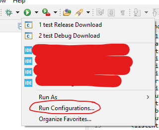
1. Got to Run configurations:


2.  Next create a new regular C/C++ Application (1), in the C/C++ Application window place the directive visible on the screenshot below (2), where downloadDebug.cmd is the script you'd like to execute after the build. Tick the "Enable auto build" radio button and select the appropriate build configuration (3). 


3. You can also place it in the favorites menu by ticking the checkbox: 

This way we can create a configuration for both Debug and Release: 

In my opinion, the gain is substantial: incremental build (with no changes) + download the old way takes ~13s, whereas the new way in the same configuration takes ~5s (build takes around 3s).

Be sure to let me know if there's an easier way!


Wednesday, February 2, 2022

IRQ logger - a simple tool for diagnosing interrupts

[NOTE: this post is deprecated. Please use STMViewer instead]

Hey there!

Today's post will be about a debug tool I've been thinking about for a while now:

I was recently designing a part of embedded software where I had to check the interrupts execution times and if their priorities are set correctly. In short, it meant I had to take my oscilloscope probes connect them with wires to the MCU's GPIOs and toggle them in each interrupt routine.  

nobody likes that...

Meh. I thought to myself, now's the time to finally do something about it. I wanted something that will show me the interrupts as logic signals in time, such as a signal is high when the interrupt is active and low when it's not. Also, the time resolution should be small enough to measure a few-microsecond interrupts. At first, I wanted to go for realtime logging like trice or directly using Segger's RRT communication, but these were too slow and added too much overhead which could cause differences in operation when logging is present vs when it's not. Moreover, I actually didn't need to send any sophisticated debug messages, just a timestamp, an ID, and a state (0 or 1). I thought I could just make a buffer in the RAM memory, collect all the data for some time (until the buffer is full), and then send it using DMA to the PC where a python script would interpret it as a time plot. I liked the idea at first but found connecting UART or any other additional cables (besides the STlink) quite annoying and not applicable to my current projects. And this is when it struck me - I could just use STlink and it's CLI to send and receive data from the target - no other communication buses are needed. It even has the -dump option to dump the binary data to a file - excellent. 

So I began by creating a struct of two timestamp variables (one is expressed in milliseconds, the other in us) - both are 2 bytes each, a 1 byte ID and 1 byte state variables. Six bytes in total. I thought about integrating the state in the ID's MSB, but for now, I decided to keep it super simple. This is the struct, with a union to be able to easily represent it as a byte array. 


The packed attribute is to avoid padding. After that, I had to set up a timestamp timer and implement a simple function that adds logs to the buffer. The embedded side of the project is really straightforward, as it was intended. 

This is how you add a log to the buffer

Next, I got to the part where I needed to read the buffer from the MCU's memory and present it as waveforms so that the data is actually useful and readable. My initial plan was to check the variable addresses in the *.elf file, insert them into the python script and use ST-Link CLI (pystlink) to read their values. This however seemed really impractical, especially when the addresses changed during the firmware development process. This is why I decided to use pyelftools for elf file parsing and variable address extraction. You just have to know the variable names and not change them during development. The script will automatically find the address of the "enable" variable (which turns logging on), and the buffer with its size. It will trigger the logging process and then download the buffer to a binary file, which can be viewed in case the target is no longer present. 

The rest is just unpacking the binary data to a list using "struct", and taking care of signal states in time so that they are displayed correctly. I also added two cursors (they still need improvements) to be able to quickly check the time period of a particular signal state. A simple example log is presented below: 


Of course, I wanted to check the performance so I conducted some tests with my scope. First I checked how long it takes to toggle a GPIO (directly using BSRR and BRR registers). The MCU's core clock was set to 170 Mhz during the tests and the optimization was turned off  (-O0) for the user files and set to -O3 for the logger source file (with #pragma GCC push_options directive).

GPIO test:


This way all the future measurements should be reduced by the 36 ns period. 

Since adding a log is the thing that happens very often and takes place in interrupts I started by measuring the time it takes to add a single log. There are two options - the delay it introduces when logging is off (only entering the add_log() function and checking the first condition), and the delay it introduces when logging is turned on (when besides calling the function we are actually writing values to the buffer). 

The first option when logging is off, takes about 200ns:


whereas the case when logging is turned on, takes twice as long with about 420 ns:


I think it's pretty decent, even considering the shortest interrupt routines. I also plan to test the add_log() function implementation as a #define, so that there's no overhead due to function call. I've heard it's not really the best practice and today's compilers are pretty aggressive with inlining functions, but we shall see ;) 

The source code can be found on my github account, together with a short step-by-step guide on how to use it. There's also a docs/photo directory with some scope and logger screenshot comparisons, and a STM32f474CCU6 example code. Please bear in mind I'm not really a Python guy so the code may not be the best quality. 

Hope you'll find it useful! 

Friday, October 22, 2021

My bachelor's thesis (brushless actuator report)

 Hey,

This time I'd like to finally share my bachelor's thesis with you. I couldn't do that earlier due to some internal regulations of my university, but since over six months have already passed I'm free to publish it by myself. 

Before you take a look at it I must say it is not an innovative approach to the subject, but rather a report about a homemade brushless actuator. There might be some mistakes along the way as I'm still learning the motor control stuff, but hopefully you'll find it at least a bit interesting ;) 

Here it is: THESIS


Tuesday, September 28, 2021

[OLD PROJECTS] DIY Smartwatches

 Hey!

Recently there was not much going on with Wolfie due to my work and vacation (chip shortage played its role too), so I decided to do a second "old projects" series writeup, this time about smartwatches I used to build. 

The whole thing started when I was attending history classes at my junior high/high school. It was a huge pain for me as I had to memorize a lot of dates and events, which is not what I was (and still am) good at. I thought I could use my engineering skills to build a device that would help me a bit during the tests and at the same time improve my PCB design/ programming skills. 

I decided to build an electronic watch with an LCD display that could not only show the time and date, but also display some small size text. I wanted to use a microSD card for storage, an AVR microcontroller, and an old Nokia display (back then it was hard to find any low-cost displays online). The hardware was pretty basic, but what about the main functionality? Basically, you'd just put some plain text file on the SD card and the watch would display and scroll the text file, when the cheatsheet function was activated. The best thing was that the cheatsheet could not be triggered unintentionally, without a special pen I was using to write tests. The pen would have a small magnet build in, and only it could activate the hidden option. This was a nice safety feature in case the teacher saw the watch displaying a wall of text and wanted to take a closer look (which actually didn't happen even once). Ok, so turning the cheatsheet on was pretty simple, but what about turning it off without much interaction with the device? I decided to implement a mechanism that would enable me to go back to the clock screen, by just using the smartwatch hand/wrist. In the first prototype, there was a flat push button on the strap, normally located under the wrist. The only thing you had to do when the teacher was approaching was to just slightly push the strap against the desk to activate the button. In the next iterations, I just added an accelerometer so that all you had to do was slightly move the hand or put it in a certain predefined position, and the text disappeared. 

I couldn't find any photos of the first prototype based on a Nokia 3310 display as it was a long time ago. I hope I find them eventually, but for now you have to believe me it actually existed :P. Since 3D printers were not as popular at the time, I remember making the case from hand-cut laminate pieces and the whole device looked a bit crappy. Even though, it worked fine and helped me (and some of my friends) to pass some of the most tedious classes. 

The next prototype was no longer only about cheating. I was inspired by my friend's Polar smartwatch that had a built-in GPS receiver and could serve also as a bike computer. I decided to upgrade my watch with a color LCD, a GPS receiver, a vibration motor, and some more features. Here's how it looked like: 

early prototype with the GPS module mounted on the strap (yeah the cables didn't last long)

Still a crappy-looking design, but not long after taking this photo I got a Prusa i2 printer and made it look a bit better: 


I created two designs, one a bit thicker with a GPS receiver and another one without the GPS option which was thinner, as I could fit the battery in a PCB cutout region. 


GPS variant - back side


GPS variant - front side

regular variant

As you can see the PCBs were made at home and looked really bad with all the fixes and Kapton tape (but hey, it worked back then!) 

I remember there was a simple menu with icons - you could even decode some *.bmp images from the CD card and check GPS coordinates, ground speed etc. It turned out the watch is a rather poor bike computer as it kept loosing GPS signal in the woods (yeah the receiver was under the PCB and the LCD...).

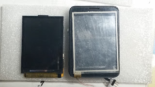
Even this watch wasn't enough - I wanted to make a touch-screen version. Unfortunately the only types of touchscreens available back then were the resistive ones that, as we all know, are rather annoying. After some search I've found out that Nokia had a nice touch panel on the C3 model, which did not require as much pressure to activate. I decided to go for it and at the same time I had to get a larger display (yes, also from Nokia phone): 

the actual Nokia touch screen is under the chineese one on the right 

 Nokia screen displaying some rectangles 
and an image (this was super exciting!)

some reverse engineering to discover which data frame I was missing

The PCB was rather crazy and till this day I'm still wondering how I got it to work without any major issues (especially since it has an external SRAM memory, the SD card is connected using SDIO bus and the LCD is controlled by a parallel 8080 bus). It was made at home using photoresist dry film and all the developing and etching processes. The thing that annoyed me the most was hand-soldering all the vias.. 
developed photoresist

etched laminate

ready PCB
other side of the PCB

The PCB contained a lot of modules like a MP3 hardware decoder with headphone amplifier, Bluetooth low energy module, wifi module, external SRAM memory (yeah on this poor 2-layer layout...), RTC, touchscreen controller and a micro SD card. Actually, it was a huge overkill especially when it comes to energy saving. 
and old graph of all the peripherals

Going for a more powerful STM32 microcontroller enabled me to make some more advanced stuff such as decoding *.JPEG photos or even playing a low frame-rate motion JPEG video (link). The cheatsheet option was still available, but this time not only using text but also photos. 

the watch with a 3D printed case 

"dark mode"

MP3 player 

The nice icons, lists and other wigets com from the STemWin library, which made he whole process of designing the menu and window much easier. 

diy calculator demo 

I remember wearing this watch everyday (and all the previous ones) and getting a lot of questions as it was quite enormous for a wristwatch. Even though, it was a nice conversation starter, especially during any "robotic" events and contests. One thing I had to remember was to take it off before taking a shower :P 


I hope you liked this piece of my projects history. I had so much fun designing those I thought it was definitely worth a blog post. Sorry for the bad quality photos, but these are the only ones I had. It seems I wasn't taking as many photos of my projects back then. In the end I must warn you - (if you havent figured it out yet) - the PCB and software design of each of these smartwatches is really poor and I would not recommend you building one. In case you were really desperate, there are some nice alternatives like this one: https://open-smartwatch.github.io/

Wednesday, August 4, 2021

It's alive!

 Hi!

In this entry, I'll go over the Wolfie assembly process and in the end, I'll show you the full-body kinematics demo of the robot. It's been a very rewarding time for me, especially when I saw the robot stand on its feet for the first time :) 

Let's start with the hip actuators mounted to the 3D-printed frame:

As you can see I started with assembling first four actuators and two opposing parts of the torso. I wanted to make sure the length of the power supply and CANFD cables I estimated is correct. They couldn't be too long as there is very little free space to fit all the actuators' cables. The two parts were joined by these side covers made from epoxy laminate. My initial idea was to make them from bent aluminum sheets, however, the bending process could be a little tricky without proper tools so I went for the laminate. I cut these on my CNC mill, making two grooves along the bend line:

Later on, I screwed them to the 3D printed frame and added epoxy adhesive in the grooves. This made them very stiff. Overall the robot structure feels stiff which is great, considering it is mostly held together by these two covers and the bottom plate. In the next revision (this is just a first prototype) I'll definitely go for inserts so that I can easily unscrew the side covers and the whole torso assembly. 

Next up there were the four thigh actuators that are mounted to the hip actuator output harnesses:

As you can see I also prepared the cables for both hip and thigh actuators, and for latter pulled them through a special duct right to the inside of the torso. Tibia actuators were mounted in the end:


They whole actuator structure is actually pretty hard to assemble, but since it's just a hobby project I decided to leave it as it is and not optimize it for now :P. 
I think just by looking at the last picture you can see the amount of connectors and cables inside the torso - its really dense in there. My plan was to use distribution PCBs like in the picture below:


unfortunately my PCB parcel got stuck in the customs and I had to mill these two by myself:


The cables look much nicer when these distribution boards are in place:   


The laminate barrier part that you see inside the torso is just a piece of epoxy laminate with some nuts glued to it: 

             
One of the last things was to put a sticky black foil on the covers so that they matched the rest of the assembly:


And finally! Wolfie the quadruped: 


I know, its missing a few parts, but still it was a big event to put all the parts together :) Moreover I got it to move a bit: 


This is just a simple demo, with kinematics implemented fully on the computer in a python script which then sends the commands to the actuators through USB<>FDCAN converter. When I finally receive the PCBs I will implement it on the raspberry PI so that it could be completely standalone. 

In the end I want to mention the presentation about Wolfie which I gave during the Reddit r/Robotics Showcase. The whole event was recorded so feel free to check that out (my presentation starts at 01:04:30): 


Now I want to tweak the walking algorithm which I'm not totally satisfied with (that's why I didn't publish it yet) and eventually implement some more advanced walking techniques, which require doing some more research :) I'll keep you posted! 

Thursday, July 1, 2021

Lots of machining!

Hello again, 

as always I did not plan to make such a long break from documenting stuff, but this time I waited to finish preparing all the parts so that the photos are as good as they can get. Basically, this entry is about making the parts needed for the remaining nine actuators and an additional tenth actuator that's going to serve as a test unit. 

The whole process took me around 1,5 months, but only because I had a few hours available every weekend (I did not want to mess up with my neighbours :P). The first step was to purchase the stock at a local company. I got around 5.5 kg of aluminium stock in 140mm diameter slices cut on a band saw.

The surface finish was quite bad so I had to face mill each side of each slice and then proceed with milling the parts. Besides face milling, each slice was drilled with seven holes to keep it fixed to the table. Each hole was widened on both sides of the slice so that the screw head could hide inside the material for the purpose of face milling.


Basically I've drilled seven 3mm holes, widened them at one end, screwed the stock to the table, face milled it, turned it around, widened holes by hand using a electric drill, screwed to the table and face milled on the other side as well. The whole process of face milling and drilling holes took me around one hour per two slices. 

When first two slices were ready I could proceed with machining parts. I didn't have any particular plan, just started with the parts I've had the least. These were the motor base parts:

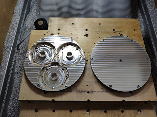
During milling I found some things I could optimize for example before I used to mill the distancing part without utilizing the material that's inside the part. It was just cut out and additionally had to be fixed so that it doesn't fly away. I found out that the material could be used to mill the planet carrier and there still will be enough material to cut the distancing part. Additionally the rest of material on the sides could be used to mill sungear mounts. I'm not the best at describing things so I prepared a photo - story of the process :


I like how these PCB caps present in the sunlight (these were actually cut out of a 6mm aluminum sheet, hence the brownish finish on the first six of them): 

I wish I had flood coolant system, as after more aggressive cuts I had to wait for the part to cool down. Moreover I had to stand nearby with a vacuum cleaner to clear the chips in deeper grooves so that they don't build up. Anyway I'm happy with the overall result - the machine did just fine, without any major issues. After all, milling these parts was actually the reason it was created. Group photo: 


After finishing all the custom parts I proceeded with motor parts and gears I had to modify slightly. The rotors were milled with four slots and the top surface was face-milled. The shaft was cut so that the encoder magnet could be glued onto it. 


The thing I'm not particularly happy about is that five out of 12 actuators have the magnets glued to the shaft without any additional fixture. The rest is actually held in place using a miniature 2mm rod going through the shaft and the magnet, because the magnets have a small hole in the center. Unfortunately I ran out of stock on them and had to use regular ones. 

The magnet on the right has a small 2mm hole which helps to align and properly fix it to the shaft

If anyone knows where to buy them (I got these from a friend of mine), I'd be grateful for leaving a comment. 

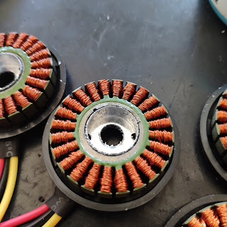
Next I cut out the stators out of the original case. It was a long and stressful process as I didn't want to mess up the windings or the laminated steel sheets. I centered each motor in a vise and bored a hole through the aluminum case leaving only around 0.4 mm of material on each side. Then I manually milled the remaining material in two opposing spots and used a screwdriver to break the walls to the inside freeing the stator. 

After that each stator was cleaned and a thermistor was glued in between the windings with expoxy.


The sungears had to be modified slightly as well. I had to mill two lobes on opposing sides so that they match the part that is screwed to the rotor. It was quite stressful as well and ended up with one broken tool (the 1.5mm 3 flute endmill) when I wanted to go a bit faster. 

When these were ready I press-fitted them onto the aluminium shafts that are visible on the photos below. 

As for now I've finished soldering the remaining PCBs, without testing them yet. Now it's time to press each stator onto the base part and make sure everything is hunky dory. Some pre-assembly family photos in the end: 


The process of tiling these parts was tedious, but I'm really happy with the photos (could use some more light though).